![]()
On this Page:
Other sections in Chapter 1:
The object of analyzing a system that models the behavior of a
chemical plant is to determine the flow rates of all chemical species
in the streams that enter and leave the plant. This tells us how much
of each raw material is used and how much of each product (along with
some wastes) are obtained from the plant. Normally this requires that
we determine the flow rates of all the species in all streams that
connect major units as well. Thus we will find it convenient to:
a) Draw a detailed block diagram of the units in the plant. (See section 1.2)
b) List and number the chemical species that will be followed.
c) List and number all streams that enter, leave or connect the units in the plant.
The block diagram could be as simple as that shown below as a generalized version of Figure 2.2 in Reklaitis
                         _______
                        |       |   ----->	Product: A+B
 Feed: A+B     ----->   | Plant |
                        |       |
                        |_______|   ----->	Waste: A+B
It (later in the course) could be as complicated as the diagram
shown in Figure P5.26 in Reklaitis.
Then we should fill in on the block diagram all the specified
information about the streams and the units in the plant. In our
simple case, the problem may say that we have a mixture of 20 mol % B
as a feed and wish to separate it into a stream containing 99 mol % A
and one containing 90 mol % B. Then the diagram would look like:
                         _______
                        |       |   ----->	Product: A+B
 Feed: A+B     ----->   | Plant |                 99% A
                        |       |
       20% B            |_______|   ----->	Waste: A+B
                                                  90% B
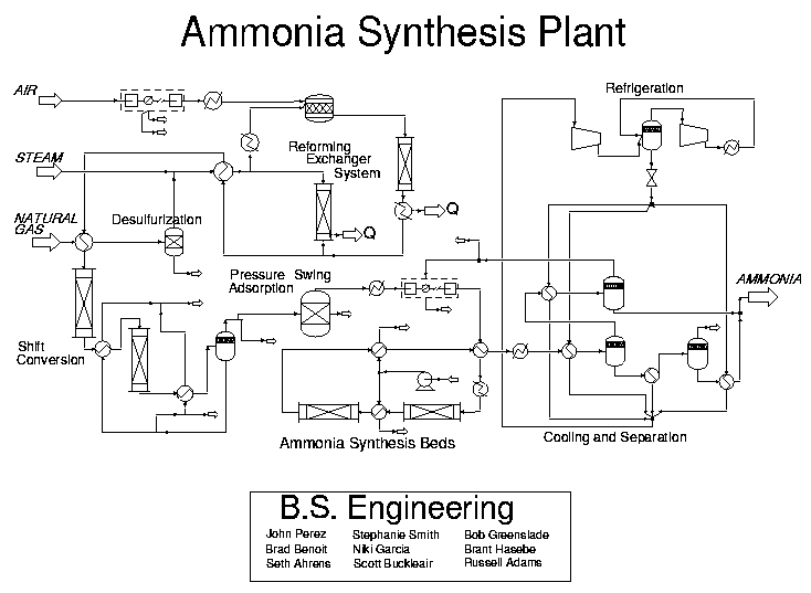
Framemaker (see CENG 303 Framemaker Notes), Word, Excel, similar PC based programs will help you draw diagrams you can print out on a laser printer. The exact program used to draw is not important, just a neat and clear presentation of the information about the process. View a (much) more complicated flow diagram here.
Once we have completed the diagram, it may be convenient to then
start filling in the information shown in the tables in section
1.1.3 below. The first of these tables gives the desired flow
rates. They are shown as molar flow rates, but in many systems mass
flows may be more appropriate. Do not confuse molar flow rates (mol
fractions) with mass flow rates (mass fractions). The second table
lists reaction rates that will be important in any plant used to
convert some compounds into others. Reaction rates are always given
in molar units.
Eventually we would like to complete all the entries in both tables.
Many of the entries are given in the problem statement. This includes
zeros for flow rates of species that are not present in certain
streams and zeros for reaction rates that do not occur in certain of
the reactors.
As an aid in determining the order of calculation for treating the
units in the plant, a degree of freedom table should be prepared for
all except the simplest systems. This calculation is discussed in
1.6.
The two tables on the next two pages illustrate a simple plant in
which there may be no more than six compounds and twelve streams. In
modern chemical plants both of these numbers could be in the
hundreds. Note that each compound flow rate that is not specified
must be treated as an unknown to be determined. Similarly each
unspecified reaction rate is an unknown. The larger this total number
of unspecified flow and reaction rates the more information we need
to solve for the plant performance.
Information that is useful in determining the plant performance
includes:
Information about the plant may be given in other forms, but these
are the most common ones for steady state chemical plants in which
energy effects are not important.
|
Comp No. |
1 |
2 |
3 |
4 |
5 |
6 |
Total |
||
|---|---|---|---|---|---|---|---|---|---|
|
Stream |
From Unit* |
To Unit* |
|
|
|
|
|
|
|
|
1 |
|
|
|
|
|
|
|
|
|
|
2 |
|
|
|
|
|
|
|
|
|
|
3 |
|
|
|
|
|
|
|
|
|
|
4 |
|
|
|
|
|
|
|
|
|
|
5 |
|
|
|
|
|
|
|
|
|
|
6 |
|
|
|
|
|
|
|
|
|
Note:To print out a more useful template of the above table, click here, then print.
|
Reactor |
|||||
|---|---|---|---|---|---|
|
Reaction |
Reaction |
1 |
2 |
3 |
|
|
1 |
|
|
|
|
|
|
2 |
|
|
|
|
|
|
3 |
|
|
|
|
|
|
4 |
|
|
|
|
|
Note:To print out a more useful template of the above table, click here, then print.
The next few sections of these notes will examine increasingly
complicated systems. They will make use of the MATLAB programs
developed for this course to take a large part of the tedium out of
the required calculations. We will start with simple modules with
exactly the right data given for them so that we can determine all
flow rates and reaction rates directly. Then we will move to simple
units with the right amount of data given but in a form that requires
more work to get all our flows and reaction rates. We will also see
examples where we need to combine some of the modules to model our
units. These combinations will be simple enough so that the final
units still involve only a few streams. Finally we will look at
plants that start to approach reality. In these the use of some
organization of the known plant data will be very useful in helping
to see where to start our solution. Thus the degree of freedom
approach is given to show how to organize the solution procedure.
1.1.2 Example and Exercise on Flow
Rates
Let's take the very simple system posed at the beginning of this
chapter on page 7 to show how we would proceed in calculating the
flows for a plant that just separates two compounds. First we note
that no flow rates were given in the statement of the problem. Thus,
we are free to choose a basis in solving the problem. A convenient
basis is 100 mols of the feed. Then without much difficulty, we can
state that the feed stream must have 80 mols of A and 20 mols of B.
We can fill this into our flow rate table as:
|
Comp |
1 |
2 |
Total |
||
|---|---|---|---|---|---|
|
Stream |
From Unit* |
To Unit* |
|||
|
1 |
Feed |
Plant |
80 |
20 |
100 |
|
2 |
Plant |
Product |
.99N2 |
.01N2 |
N2 |
|
3 |
Plant |
Product |
.10N3 |
.90N3 |
N3 |
We also know that the amount of A in the two streams must be 80.
Thus:
Solving
these two equations in MATLAB, we find:
>> [1 1; .99 .1]\[100 80]'
ans =
   78.6517
   21.3483
Thus we can fill in the rest of our table and check the MATLAB
solution.
|
Comp No. |
1 |
2 |
Total |
||
|---|---|---|---|---|---|
|
Stream |
From Unit* |
To Unit* |
|||
|
1 |
Feed |
Plant |
80 |
20 |
100 |
|
2 |
Plant |
Product |
77.8652 |
.0.7865 |
78.6517 |
|
3 |
Plant |
Product |
2.1348 |
19.2135 |
21.3483 |
If you cannot immediately see that the flows make sense in that
both A and B are conserved, you should be able to do so later
in this course.
Suppose the molecular weight of A is 40 and that
of B is 20. A program that converts from mol fractions to mass
fractions is called moltomas. Help used on this
function gives:
>> help moltomas
  function w=moltomas(x,mw)
  x gives the mol fractions of the compounds in a stream
  mw gives the molecular weights of the compounds
  w returns the mass fractions of the compounds
The mass fraction of the feed and product streams would then be
found by:
>> mw=[40 20];
>> moltomas([.8 .2],mw)
ans =
    0.8889    0.1111
>> moltomas([.99 .01],mw)
ans =
    0.9950    0.0050
>> moltomas([.1 .9],mw)
ans =
    0.1818    0.8182
As an exercise, pick 100kg of the feed as a basis and find all the
flows in the feed and product streams in mass units. Show that the
answers obtained in mass units are consistent with those found in the
mol flow rate example.