|
On this page I will introduce you to the various tools and tricks that exist to help you make important decisions about your plant and to help you work as a team. This Page will cover the DataBook, the use of template subflowsheets, and my process "switch".
|
|
|
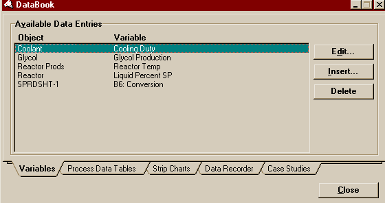
Use Insert... to add a new variable to the list (the new variable will be added above the selected variable), Edit... to, well, edit the selected variable's name or the very choice of process variable itself, and Delete should be obvious. You can choose any process variable to add to the list (see my Case Study Example to see one of the few exceptions I have found). Pressing Edit or Insert, will cause the Variable Naviagator to appear. Choose the process variable you want from there.
The Process Data Tables
If the process variables in your simulation are like all the various goods in a grocery store, than the Process Data Tables are like your grocery basket in which you pile only those variables from around the store that you wish to monitor. Essentially, you just tell the DataBook which of the Variables defined on the Variable Page you wish to show in the Tables and the Process Data Tables will always show the current values of those variables. It's a good way of assembling information from all over the flowsheet into one, easy to view, place. All of the tutorials in the Tutorials Book show examples of its use.
Important: At the time of this writing, the version of HYSYS we are using (ver. 1.2.11) has a bug in the Process Data Tables. No matter what units it says it is displaying, HYSYS is actually displaying the variables in its internal units. Thus, at the moment the Tables are not really of much use, but it should be fixed in the next upgrade.
The Data Recorder
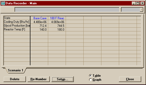
Like with the Process Data Tables, the Data Recorder make work with any of the Variables that have been defined on the Variables Page. The purpose of the Data Recorder is to provide you with a way to keep a record of your values even after you have changed your simulation, much like taking a snapshot. It is good for making a benchmark and watching your progress, as well as giving you a record of which combination of parameter values gave which results.
|
|
If you wish to delete an individual entry, delete its title. If you press the Delete button at the bottom, it will delete the whole Scenario and there is no way of getting it back without repeating the whole chart all over again.
You will find examples of its use in any of the tutorials in the Tutorials Book.
Case Studies
I think the most useful of the DataBook tools, the Case Study allows you to quickly vary key process variables across a range and observe the effect on other key process variables. While you may choose any number of independent and dependent variables for the Case Study, HYSYS will only plot a maximum of three variables at a time. One independent variable and one or two dependent variables make a 2D graph and two independent and one dependent variable make a 3D graph. Should more dependent variables be included than the one or two allowed for plotting, HYSYS will use for the graph the first one or two dependent variables that are checkmarked Active on the Display Properties Page of the Case Studies Setup. Check out my example where I show you in greater depth the uses and limitations of the Case Study.
Templates and Sub-Flowsheets
Templates and their use as Sub-flowsheets are going to be the key to your group working as a team on design. This will be especially true when you get to CENG 404 where you will be designing an entire plant. You will find, especially in 403 that it is far too easy too let one or two people in the group do all the simulation work. Don't be tempted, because when you get to 404, it is far too much work for any one or two people to do. You will be glad if everyone in your group got good practice simulating reactors, columns, and heat exchangers (as well as all the other ops you will use) back in 403.
Now, since it is so easy for one person to claim a flowsheet, because he or she did so much work on it that he or she is the only one who knows enough about what is going on to work on it, you must find ways of either sharing the work or splitting up the flowsheet.
Of course, you could just agree to only work on the flowsheet when everyone is present and hover over one computer (which might actually work well for 403 if your schedules match well enough). However, you don't get any division of labor that way. If two people do want to work on the simulation at the same time, you have to use Save As to make a copy and then there is no way to recombine the work, so one person's changes must all be scrapped or laboriously transferred over to the other file at the end.
There is another option, but it requires a little forethought. You've seen how when you open the Property View of a Column, you have the option of entering its Column Environment. Therein you see the column has its own PFD with streams and units that may be hidden from the main flowsheet. There are two other kinds of sub-flowheet besides that of the Column. They are the templates that you import in and the sub-flowsheets that you create in-situ. Once they are installed there is absolutely no difference between them (unlike with the column, which does have a slightly different form of environment). A template is created just like any other case (in fact, any simulation can be converted to a template to be used in another simulation). The only difference is that a little more information is needed to guide HYSYS in transfering info between the main simulation and the "black box" that is the Sub-flowsheet.
It is a very modular way of doing things. Even if you don't need to reuse a section of plant or use it another simulation, the templates are a great way of breaking a complicated flowsheet down into more manageable chunks. The best part, of course, is that templates are separate files and thus solve your problem of working as a group. One scenario could be to assign a section of plant to each person or a pair of people and then set someone to coordinate them and put together the main flowsheet (this means a lot of deleting old templates and then reloading and reconnecting the updated templates, but it is still the easiest way of putting people's work together).
|
|
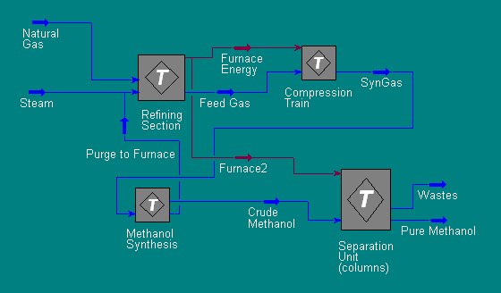
The above PFD is only an illustration to give you an idea of how you might split up a plant. A real, working PFD would doubtless have other units on the main flowsheet and at least a few few more and possibly many more energy streams connecting sub-regions. Not as many as you might think, however. One of the biggest demands for cross-regional interaction is for heat exchangers and HYSYS already has taken care of that. HYSYS allows you to place the tube side of a heat exchanger in one sub-flowsheet and the shell side in another. Thus, there could in fact many streams exchanging energy with each other between flowsheets and it does not clutter the main flowsheet up (but you might consider making adding text beside each such heat exchagner to remind you what the other half is without having to open a property view everytime). I have made a quick demonstration of splitting a heatexchanger between to sub-flowsheets. There is also an excellent example showing how it can be done between the main flowsheet and a sub-flowsheet with a refrigeration loop in Section 15.3.4 of RV2.
There are some other issues that must be dealt with when using sub-flowsheets. One of the best features that the separate environments have is the ability for you to use different fluid packages in each sub-flowsheet or column flowsheet from the one used for the main flowsheet. For instance you might want to use an EOS for a Natural Gas Reforming Section and a thermodynamic package more suited for VLE or LLE in the Separations Section or Columns. Just removing components from a fluid package in areas they are not needed will reduce HYSYS' convergence time.
Of course, with the ability to use different property packages in different sections of the plant, the problem of passing information from one region pops up. You know that any two of Vapour Fraction, Temperature, Pressure, and Enthalpy, plus the Composition of the Stream is enough information for HYSYS to flash the stream and find the rest of the information. You should expect that the same two parameters in Peng-Robinson will give different results for the rest of the variables then if the thermo package were Antoine (an essentially ideal package). So if you need to pass a stream from a flowsheet using PR to one using Antoine or vice versa, it becomes important to decide which pair of parameters should be used to flash the stream on the other side. That's what the Transfer Basis is for.
On the Transfer Basis Page of the sub-flowsheet Property View, next to each stream, you may pick one of the following choices for a transfer basis:
- P-H Flash - Pressure and Enthalpy Passed (Not Recommended)
- T-P Flash - Temperature and Pressure Passed
- VF-T Flash - Vapour Fraction and Temperature Passed
- VF-P Flash - Vapour Fraction and Pressure Passes
- None Required - Nothing passed. Normally used for energy streams, though if used for material streams, will still pass composition (though suprisingly not flow)
- User Specs - User Specified (to the best of my knowledge, essentially the None Req'd when actually intended for use with material streams)
I have prepared an example demonstrating the importance of choosing the correct Transfer Basis.
You've probably noted that I have yet to discuss or include in my examples, the means by which you should actually go about making a template. In my examples, I had you create blank sub-flowsheets to build on within your cases. When you actually are working on your projects, this is NOT the way you want to do things. If you start with a blank sub-flowsheet there is no simple way to turn it into a template (there is a work-around which I will discuss later but it is not pleasant either to do or work with later).
If, on the other hand, you were smart and divided your plant up into pieces early on, you could build the pieces separately as templates or as separate cases (which may be converted into templates) right from the beginning. Even if you started by placing everything in the main flowsheet, you are still good because you can save the file under a new name then delete everything but what you want to put into a sub-flowsheet and then convert the case to a template.
To show you how this may be done, I am putting a short example right here.
TEMPLATE EXAMPLE
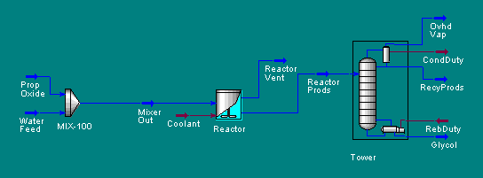
Start with ChemicalsEx.hsc in my sample directory or TUTOR3.hsc in HYSYS' sample directory (they are the same thing). It was the one that looked like this
|
|
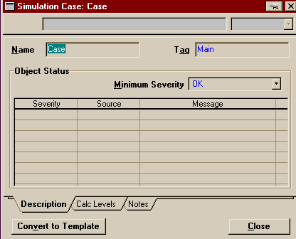
The first thing you must do is save the file under a new name (you shouldn't be able to write to either directory anyway). Now, let us pretend that this flowsheet represents not an entire process, but merely a section of the plant we wish to model. We'd like to convert this case into a template. To do that, go to the Simulation Menu and choose Main Properties. Here you can change the name of the case or its tag, or, on the Notes Page, you can write the description that appears next to the file name in the Open dialog window. However, we are here for the button at the bottom.
|
|
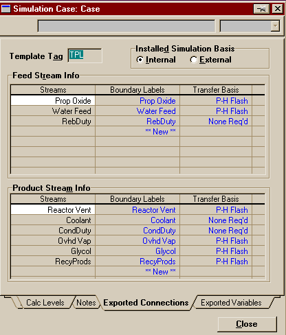
Press Convert to Template. After HYSYS asks for confirmation and you approve it, HYSYS will close the case you were working on (it will ask if you want to save it first) and leave open the newly created template. The template, of course, looks the same as the case except that the file name at the top shows the extension .tpl instead of .hsc and some new pages have been added to the Main Properties window we have been working with.
|
|
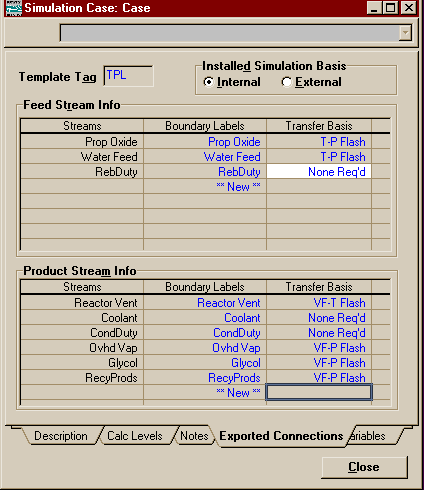
On the Exported Connections Page, you have a number of options for the default values connected with the template when you import it as a sub-flowsheet. At the top you may choose the tag it will receive in the new flowsheet and whether the default property package should be that of the template or that of the simulation it is imported to. You can, of course, change the property package of any sub-flowsheet after it has been imported from the simulation basis manager.
You can also affect the
name of the streams as they will appear on the
sub-flowsheet's Property View to be connected with streams
on the main flowsheet and the transfer basis of each stream.
Let us put to use the concepts I taught in my transfer
basis example and pick the transfer bases for these
streams.
The None Req'd type is
fine for our energy streams, but you'll remember that P-H
Flash is definitely not good for the material streams.
The two material feed streams were defined by specifying
their temperature and pressure, so they should probably be
set to T-P Flash. The three streams exiting the
column are all from the condenser or reboiler and are
saturated vapours or liquids. Therefore, they should be set
to VF-P Flash. In general, all direct product streams
from a column should be set to either VF-P or VF-T
Flash. The last product stream, the vent from the
reactor is also the result of a flash separation. Moreover,
it had its temperature set directly (via the stream
Reactor Prods) and so should be set to VF-T
Flash. Note that the choice of T or P is much less
important than the choice of Vapour Fraction as the other
passed parameter in these cases.
|
|
You are now ready to install the template as a sub-flowsheet in another simulation case. I hope the information I have imparted to you makes it easier to turn your projects into real team efforts.
Oh, one last thing on this. If it should happen that you created a subflowsheet from scratch that you really want to turn into a template, the work around is to save the file under a new name, eliminate everything from the flowsheet except the sub-flowsheet and the streams directly connected to it. Then, turn this into a template. This process adds another level of depth (and irritation) between the areas you want to work with, but it does work.
The Process "Switch"
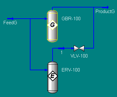
This is one trick that is not mentioned anywhere in the HYSYS manuals, but it works regardless. If you've gone through my Gibbs/Equilibrium Reactor Example than you've already seen what it can do. Essentially there is a way in HYSYS to choose one or another "path" for a flow. Somewhat like a switch in a railroad track that sends the train to another destination, you can send a stream to more than one unit operation or section of the plant to evaluate how they compare to each other and then merge the "tracks" on the other side to see the effect downstream in the plant of using the one over the other.
|
|
This is the picture from the example I mention above. You see how the stream appears to diverge then reconnect. The stream is not actually splitting and mixing. It must go one way or another. In the picture the Equilibrium reactor is active and the Gibbs reactor is Ignored, but it can be switched easily. To see the process of setting up a switch, see my example.
