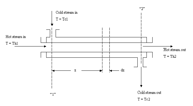
This project describes the performance of the simple double-pipe heat exchanger shown in the following figure in terms of the heat-transfer coefficients of the two streams and the thermal resistance of the pipe wall. The exchanger consists essentially of two coaxial pipes with one fluid stream flowing through the inner pipe and another in the annular space; heat is transfered across the wall of the inner pipe. Both streams may flow in the same direction, as indicated in the figure, but normally it is more efficient to use counter flow, that is , to reverse the direction of one stream relative to the other. Steady state turbulent flow may be assumed, and heat losses to the surroundings may be neglected.

Sample Problem:
a.) Hot oil entering the heat exchanger in the above example at surface "2" is to be cooled by water entering at surface "1"; that is, the exchanger is being operated in counter flow. Compute the required exchanger area A if the heat-transfer coefficient U is 200 Btu/(hr* ft^2* F) and the fluid streams have the following properties:
lbm/hr |
Btu/(lbm*F) |
|||
b.) Repeat the calculation of part (a) if U1=50 and U2=350 Btu/(hr*ft^2*F). Assume that U varies linearly with water temperture, and use the following relation:
