Implementation of Transform Coder using DCT
Our group implemented the 2 dimensional DCT transform in an image coder.
The coder compresses 256*256 images. The coder divides the image
into 8*8 subimages and separately applies the DCT to these sub-images. The
DCT is a unitary (one to one) transform. It transforms the image from the
spatial domain to the frequency domain. The DCT provides a performance for compression which is close to the optimal Karhunen-Loeve transform.
Definition of the DCT
DCT Vs. FFT
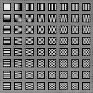
Basis Functions of the DCT
The DCT
Computation of the DCT
The values obtained using the discrete cosine transform are scaled so as
to be represented by 8 bits. This includes 1 bit for the sign. The values
range from -127 to 127. The number of bits for each value is determined
according to a specified bit mask. The transform has large values at the lower
frequencies. This is because most of the energy in the image is
concentrated at the lower frequencies. A large number of bits are assigned
to these values while fewer bits are assigned to the values corresponding
to higher frequencies. For example, 8 bits may be used to represent the
value of the DCT at low frequencies, while 1 bit for the higher
frequencies. The average number of bits/value is determined from the bit mask.
This step results in lossy coding. Information about the original image is
lost. However a certain compression ratio is achieved. These bits are then
written to a file along with mask information.
There is a definite relationship between the average number of bits per
value of the DCT and the quality of the image. The lower the number of
bits/value, the lower the quality of the resultant image.
The inverse coder takes the quantized transform values from the file and
applies the inverse discrete cosine transform. The image obtained has a
quality proportional to the number of bits assigned per pixel in the bit
mask.
The Inverse DCT
Back..