Example 2: Cooling the HDA Reactor Streams Using HTXCC3
The effluent from the reactor in HDA process needed to be cooled before it could be sent to a flash unit. It appeared as stream 1 in the section of flash units.
             Inlet     |                Outlet
   Stream            1 |            2          3   Total
  Tmp K         929.00 |       300.00     300.00
  State         vapor  |       vapor     liquid
  Enthalpy -50020930.3 | -176426148.5  7900057.8 -168526090.7
Compound    Stream Flows
 toluene       28631.5 |       1039.2    27592.3      28631.5
 hydrogen     795956.6 |     795431.9      524.7     795956.6
 benzene      150568.2 |      16569.3   133998.8     150568.2
 methane     2387533.0 |    2378826.1     8706.9    2387533.0
 biphenyl       5726.3 |          0.2     5726.1       5726.3
Total        3368415.7 |    3191866.8   176548.9    3368415.7
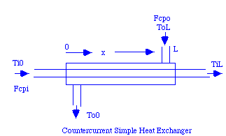
The two heat exchanger functions htxcc1 and htxcc3 simulate the same system. It is shown below:

|
We will reproduce the process stream shown in the table, but make a data file that includes water since that is probably what will be used to do at least part of the cooling. The "help" comments for the heat exchanger function htxcc3 show:
>>help htxcc3

  Htxcc3 - Counter current heat exchanger, vary one flow to
meet temp. spec.
  function [Q,Fcpo,A]=htxcc3(Ti0,TiL,ToL,Fcpi,To0,U,dTmin)
  Counter Current Heat Exchanger
  Argument List
  Ti0    Inlet temperature of inner fluid
  TiL    Exit temperature of inner fluid
  ToL    Inlet Temperature of outer fluid
  Fcpi   Flow*heat capacity of inner fluid
  To0    Exit Temperature of outer fluid
  U      Overall Heat Transfer coefficient
  dTmin  Minimum approach temperature
  Return List
  Q      Heat Transfer Rate from outer to inner fluid
  Fcpo   Flow*heat capacity of outer fluid
  A      Required Heat Transfer Area
  Example:
  >> [Qx,Fcpo,Area]=htxcc3(60,150,160,25,100,50,10)
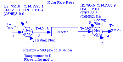
In using htxcc3, we must specify the inlet and exit temperatures of both fluids and the flow*heat capacity of one of them. We would like to cool our process stream from 929K to its dew point to avoid condensation.

|
According to the problem the reactor operates at 500 psia (or about 34.47 bar). The dew points can be determined after loading the new data file and setting the flows for the stream. In setting flows in the following use of the mass and energy balance modules, we will use kg mols/hr as our units for flow. The energy unit must then be multiplied by 1000 when we use the heat exchanger programs.
>>showe(3,4,12,3)

            Inlet     |   Outlet
   Stream           3 |           4
  Tmp K        929.00 |      437.23
  State        vapor  |      vapor
  Enthalpy   -50065.0 |   -144720.1
Compound    Stream Flows
 hydrogen     795.600 |     795.600
 methane     2386.900 |    2386.900
 benzene      150.600 |     150.600
 toluene       28.500 |      28.500
 biphenyl       5.600 |       5.600
Total        3367.200 |    3367.200
The heat needed to be removed to cool the product stream is: 9.466e7 kJ/hr (determined by subtracted the stream enthalpies). We could do this with superheated steam and would find our exchanger to have temperature variations that are similar to those just seen, but the roles of the process stream and steam would be reversed. We will look at another extreme in which we investigate the use of cooling water. If cooling water is used, there is usually a specified range for its temperature. Typically, it is fed at 90 °F (or 305.37K) and must not be heated beyond 120 °F (322.04K). Here is the flow*heat capacity for the exit process stream:
>>Qexit=9.466e7;
>>Fcpi=Qexit/(929.00-437.23)
Fcpi =
   1.9249e+05
We will postpone determining the overall heat transfer coefficient: U and set it equal to one in executing the heat exchanger program. Again the value returned for area must then be interpreted as U*A. Thus our arguments to htxcc3 have the values:
| Argument | Holds | Value |
|---|---|---|
| Ti0 | Temp. of inner fluid at left end of exchanger. | 929.00 |
| TiL | Temp. of inner fluid at right end of exchanger. | 437.23 |
| ToL | Temp. of outer fluid at right end of exchanger | 305.37 |
| Fcpi | Flow*heat capacity of inner fluid. | Value put in Fcpi |
| To0 | Temp. of outer fluid at left end of exchanger | 322.04 |
| U | Overall Heat Transfer coefficient. | 1 |
| dTmin | Minimum Approach temperature. | 5 |
>>[Q,Fcpo,A]=htxcc3(929,437.23,305.37,Fcpi,322.04,1,5)
Q =
  -9.4660e+07  <-- heat transferred from the outer fluid
Fcpo =               to the inner fluid.
   5.6785e+06  <-- required Flow*Heat capacity of the water
A =
   3.0419e+05  <-- U*A
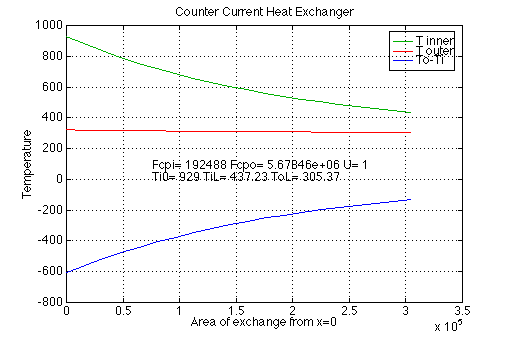
We can check htxcc3 against the first program (htxcc1) now that we know the value of flow*heat capacity of the water. In addition, we can again see how the temperatures vary along the exchanger. Giving an eighth argument to htxcc1 of 20, causes the program to plot the temperatures using 20 points for each curve.
>>[Q,To0,A]=htxcc1(929,437.23,305.37,Fcpi,Fcpo,1,5,20)
Q =
  -9.4660e+07
To0 =
  322.0400
A =
   3.0419e+05

|
Note that this time the temperature difference varies considerably along the exchanger and is much larger than in the first exchanger.
If we want to determine how much water is required to cool the process stream, we can follow the same procedure as in the first case:
>>Q/(Hinkj(322.04,'l',3)-HinkJ(305.37,'l',3))
ans =
  -7.5485e+07   <-- Negative of water needed in mol/hr
>>ans*mw(3)/1000
ans =
  -1.3599e+06   <-- Amount of water needed in kg/hr
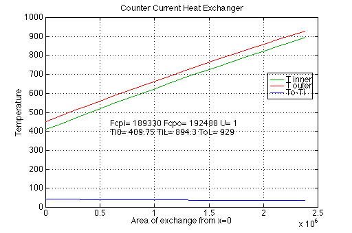
Rather than using water to cool the reactor effluent and steam to heat the feed stream, it would be more efficient to use a single exchanger in which the effluent is used to heat the feed stream. This is feasible since the reaction is exothermic. We can see that the heat transferred in the feed exchanger is less in magnitude than that for the effluent. Thus we will not quite get the effluent stream to its dew point. Thus we will use the feed stream as the "inner" stream in htxcc1:
>>Fcpo=Fcpi
Fcpo =
   1.9249e+05
>>Fcpi=1.8933e+05;
>>[Q,To0,A]=htxcc1(409.75,894.3,929,Fcpi,Fcpo,1,5,20)
Q =
   9.1740e+07
To0 =
  452.4005
A =
   2.3805e+06
Thus the effluent will be cooled to 15K above its dew point.

|