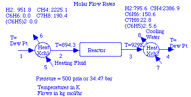
Example 1: Heating the HDA Reactor Streams Using HTXCC1
The effluent from the reactor in HDA process needed to be cooled before it could be sent to a flash unit. It appeared as stream 1 in the section on flash units.
             Inlet     |                Outlet
   Stream            1 |            2          3   Total
  Tmp K         929.00 |       300.00     300.00
  State         vapor  |       vapor     liquid
  Enthalpy -50020930.3 | -176426148.5  7900057.8 -168526090.7
Compound    Stream Flows
 toluene       28631.5 |       1039.2    27592.3      28631.5
 hydrogen     795956.6 |     795431.9      524.7     795956.6
 benzene      150568.2 |      16569.3   133998.8     150568.2
 methane     2387533.0 |    2378826.1     8706.9    2387533.0
 biphenyl       5726.3 |          0.2     5726.1       5726.3
Total        3368415.7 |    3191866.8   176548.9    3368415.7
The two heat exchanger functions htxcc1 and htxcc3 simulate the same system. It is shown below:
|
We will reproduce the process stream shown in the table,
but make a data file that includes water since that is
probably what will be used to do at least part of the
cooling. The "help" comments for the first heat
exchanger function shows:
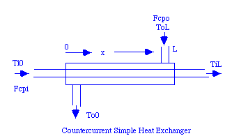
>>help htxcc1

  Htxcc1 - simple counter current heat exchanger
  function [Q,To0,A]=htxcc1(Ti0,TiL,ToL,Fcpi,Fcpo,U,...
   dTmin,nplt)
  Counter Current Heat Exchanger
  Argument List
  Ti0    Inlet temperature of inner fluid
  TiL    Exit temperature of inner fluid
  ToL    Inlet Temperature of outer fluid
  Fcpi   Flow*heat capacity of inner fluid
  Fcpo   Flow*heat capacity of outer fluid
  U      Overall Heat Transfer coefficient
  dTmin  Minimum approach temperature
  Return List
  Q      Heat Transfer Rate from outer to inner fluid
  To0    Exit Temperature of outer fluid
  A      Required Heat Transfer Area
  nplt   If given is the number of points to plot
  Example:
  >> [Qx,TAout,Area]=htxcc1(60,150,160,25,35,50,10,20)
We can see that if we use htxcc1, we need to specify the inlet and exit temperatures of one fluid and the inlet temperature of the other fluid. We also need to specify the flow*heat capacity of both fluids.
|
According to the problem the reactor operates at 500 psia
(or about 34.47 bar). The dew points can be determined
after loading the new data file and setting the flows
for the stream. In setting flows in the following
use of the mass and energy balance modules, we will use
kg mols/hr as our units for flow. The energy unit must
then be multiplied by 1000 when we use the heat exchanger
programs.
>>start403b
Copyright 1996 Rice University
All rights reserved

If you have not run the FORTRAN program start403a to
produce a data file, do so now.
<-- Specifying HDA2 with water added to our 5 compounds.
How many streams will there be?9
Here are your compounds' names:
 hydrogen
 methane
 water
 benzene
 toluene
 biphenyl
Here are your reactions:
 H2       +  C6H5CH3   -->  CH4      +  C6H6
2 C6H6      -->  H2       +  C6H5C6H5
>>nsin=[951.8 2225.1 0 0 190.4 0];
>>nsout=[795.6 2386.9 0 150.6 28.5 5.6];
>>zsin=nsin/sum(nsin)
zsin =
0.2827    0.6608         0         0    0.0565         0
>>zsout=nsout/sum(nsout)
zsout =
    0.2363    0.7089         0    0.0447    0.0085    0.0017
Our current version of dewpt does not work well for zeros stored as mol fractions, so these were replaced by very small numbers:
>>zsin([3 4 6])=1e-7*[1 1 1]
zsin =
    0.2827    0.6608    0.0000    0.0000    0.0565    0.0000
>>zsout(3)=1e-7
zsout =
    0.2363    0.7089    0.0000    0.0447    0.0085    0.0017
Then we can find the dew points:
>>Tdpin=dewpt(3447,zsin)
Warning: Divide by zero
Warning: Divide by zero
Warning: Divide by zero
Warning: Divide by zero
Tdpin =
  409.7524
>>Tdpout=dewpt(3447,zsout)
Warning: Divide by zero
Warning: Divide by zero
Tdpout =
  437.2254
The warnings about dividing by zero do not seem to interfere with final results. Now lets set streams one to four in ne:
>>setne('v',1,Tdpin,nsin)
>>setne('v',2,894.3,nsin)
>>setne('v',3,929,nsout)
>>setne('v',4,Tdpout,nsout)
>>showe(1,2,12,3)
            Inlet     |   Outlet
   Stream           1 |           2
  Tmp K        409.75 |      894.30
  State        vapor  |      vapor
  Enthalpy  -141790.8 |    -50047.2  <-- 1000 kJ/hr since
Compound    Stream Flows             <-- these are in kg mol/hr
 hydrogen     951.800 |     951.800
 methane     2225.100 |    2225.100
 toluene      190.400 |     190.400
Total        3367.300 |    3367.300
Thus the heat needed to raise the feed to the reactor temperature is 9.174e7 kJ/hr (determined by subtracted the stream enthalpies). Since the critical point of steam is:
>>critT(3)
ans =
  647.3000
it is unlikely that we would want to heat the reactor inlet gases with steam. We would have to use superheated steam that could be quite expensive. For illustrative purposes, we will show how this can be done, but keep in mind that other solutions are more efficient. Let's assume we use steam that will be about 5K hotter than the gases that need to be heated. Thus the steam will be cooled from 900K to 415K. How much we will need depends on its pressure. If we use low pressure steam (so the energy balances of our Matlab programs are valid):
>>dHsteam=HinkJ(900,'v',3)-HinkJ(415,'v',3)
dHsteam =
   17.9591
>>Qinlet=9.174e7;
>>Nsteam=Qinlet/dHsteam/1000
Nsteam =
   5.1083e+03     <-- kg mol/hr of steam
The flow*heat capacity term for each stream in the first heat exchanger can be estimated from:
           (enthalpy out - enthalpy in)
   Fcp =  __________________________________
          (temperature out - temperature in)
If we think of the process gas as being in the inner tubes and the steam outside these tubes, then our two flow*heat capacity terms are:
>>Fcpi=Qinlet/(894.3-409.75)
Fcpi =
   1.8933e+05
>>Fcpo=Qinlet/(900-415)
Fcpo =
   1.8915e+05
We can now find out what the heat exchanger program htxcc1 can tell us. Note that the seventh argument gives the minimum approach temperature for the exchanger. Heat can only be transferred from one fluid to the other if the temperature difference is always the same sign. Specifying a minimum approach temperature assures us that this requirement is met. The larger the approach temperature the more conservative our design will be. Generally it is taken to be in the range from 5 to 10K. We will use 5K in this simulation. The last argument (if included) gives the number of points to plot on a figure showing the variation of inner and outer temperatures as well as the difference between them. Here is a table listing the arguments we will use in htxcc1:
| Argument | Holds | Value | |
|---|---|---|---|
| Ti0 | Temp. of inner fluid at left end of exchanger. | 409.8 | |
| TiL | Temp. of inner fluid at right end of exchanger. | 894.3 | |
| ToL | Temp. of outer fluid at right end of exchanger | 900.0 | |
| Fcpi | Flow*heat capacity of inner fluid. | Value put in Fcpi | |
| Fcpo | Flow*heat capacity of outer fluid. | Value put in Fcpo | |
| U | Overall Heat Transfer coefficient. | 1 | |
| dTmin | Minimum Approach temperature. | 5 | |
| nplt | Number of points to plot. | 20 |
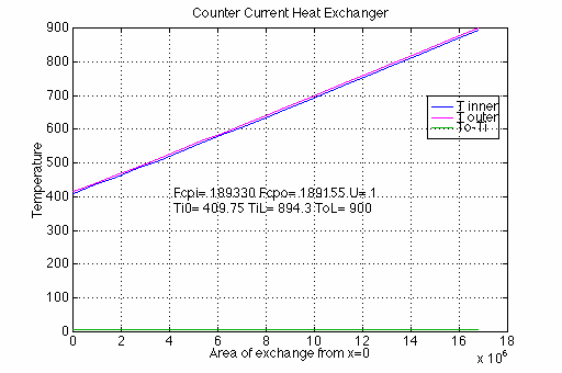
>>[Q,To0,A]=htxcc1(409.75,894.3,900,Fcpi,Fcpo,1,5,20)
Q =
    91740000   <-- Note that the heat transfer rate = Qinlet
To0 =
   415         <-- This agrees with the exit temp. of steam.
A =
   1.6766e+07  <-- This gives U*A since U=1 was used.
A separate calculation would be needed to find the heat transfer coefficient before we could actually predict the required heat exchanger area.
|
Note that the temperature difference between the streams is almost constant over the entire length of the exchanger.