1.0 Executive Summary
2.0 Process Description
3.0 Market Analysis
4.0 Reactor Design
4.5.4.1 Process Side
4.5.4.2 Shell Side
4.5.5 Conversion and Selectivity
4.5.6 Reactor Concentration Profile
5.0 Safety
5.2.1 Prevention of Backflow
5.2.2 Storage Inertion
6.0 Economics
7.0 Conclusions and Recommendations
8.0 References
9.0 Appendices
At the request of Celanese Clearlake Ethylene Oxide Production Engineer, Jeff Anderlik, JChem, Inc. studied the replacement of Celanese's existing kerosene cooled ethylene oxide reactors with water cooled reactors in order to increase production capacity. JChem determined through careful research and simutition in Aspen Plus, that Celanese must replace the existing four reactors with three shell and tube, water cooled, recycled plug flow reactors. These measures would increase capacity from 600 mmlbs per year of ethylene oxide to 1,000 mmlbs per year of ethylene oxide. Economic analysis of the project marginal cash flows resulted in a rate of return of 62.1% and a net present value of $62,875,614, assuming a 20 year operating life and a cost of capital of 13%.
In an ethylene oxide reactor, ethylene is partially oxidized over a silver catalyst to form ethylene oxide. Two of the three reactors would be maintained at all times at the following specifications. (The third reactor would be used for emergency operation or during catalyst replacement.) :
During ethylene oxide production, safety is of primary concern. The following safety precautions are recommended:
JChem believes that the execution and completion of this project is in the best economic interest of Celanese and recommends that this project be carried out immediately.
2.0 Introduction
2.1 Existing Process
The existing reaction section of the Celanese Clearlake Ethylene
Oxide Unit is centered around four shell and tube, recycled plug
flow, kerosene cooled reactors. The recycle stream entering the
reactors consists primarily of oxygen, ethylene, and a dilutent,
methane, to keep the system nonexplosive. As the stream passes
through the reactor, ethylene and oxygen react to form ethylene
oxide, carbon dioxide, and water. After leaving the reactor,
the effluent stream is cooled down on the tube side of a
feed/effluent exchanger. At this juncture, a small make-up stream of
methane is added. The recycle stream then passes through
a water absorber to remove ethylene oxide and water from the
process. Next, an inerts purge is taken from the system and the
remainder of the recycle stream is compressed. After
compression, a carbonate scrubber removes carbon dioxide from the
process. Fresh ethylene and oxygen are then added to the
recycle loop and the stream then passes through the shell side of the
feed/effluent exchanger before entering the reactor. The
ethylene and oxygen streams were assumed to be 100% pure, whereas in
reality, these streams are approximately 99.8% and 99.5% pure,
respectively (Davis)(Meyers 1.5-10). The current nameplate
capacity of the existing plant is 600 mmlbs per year of ethylene
oxide (Anderlik).
2.2 Recommended Process
The primary change to the existing process that JChem recommends is
the replacement of the four existing kerosene cooled reactors
with three water cooled reactors. The existing Celanese
kerosene reactors are heat removal limited (Anderlik).
Therefore, the reactors were sized on the basis of heat transfer
area. Water cooling allows for better heat removal in a
reactor. This allows the recommended reactors to be
much smaller in size. Furthermore, by increasing the rate of
heat removal, production rates can be increased to 1,000 mmlbs per
year. It is assumed that the current compressor can handle
increased recycle rates. In addition, only two of the three
recommended reactors would be in service at any given time.
This allows for catalyst changeout and maintenance work to be done on
the reactor that is shut down.
A flowsheet of the recommended process was modeled in Aspen Plus
and is shown below. Please refer to the appendix for the
corresponding material balance.
JChem does not recommend the coversion to air as the oxygen feed. Plants using air as a source of oxygen require a large inerts separation section in the unit to remove nitrogen and argon introduced into the system. Celanese Clearlake has neither the plot space nor any economic advantages for switching to air. Oxygen is available cheaply from many different local sources. In general, air based plants have higher capital costs, lower yields, lower safety concerns, and higher catalyst replacement costs (Meyers 1.5-9). Furthermore, industry studies conducted in 1976 concluded that the use of oxygen is at least as economically beneficial as the use of air in a large scale (>550 mmlbs per year) ethylene oxide plant (Kiguchi et al 69)(Gans et al 73)(DeMaglie 78).
For this project, the water and carbonate scrubbers were assumed to be 100% efficient and were modeled using AspenÕs Sep unit operation. Following a detailed design, this project could be constructed in the first quarter of 1998.
3.0 Market Analysis
3.1 End Uses
Ethylene oxide is used internationally in the following capacities
(Chemical Week Web):
|
|
|
|
Monoethlyene glycol |
58 % |
|
Ethoxylates |
18 % |
|
Diethylene and Triethylene glycol |
7% |
|
Ethanolamines |
6% |
|
Glycol ethers |
4% |
|
Polyols |
3% |
|
Polyethylene glycol |
1% |
|
Other |
3% |
3.2 Demand
Since a large percent of ethlyene oxide is used to produce
monoethylene glycol, demand of ethylene oxide fluctuates with the
demand for monoethylene glycol. Demand for monoethylene glycol
is highest during the antifreeze blending season, which starts in
May. The market is fairly tight throughout the season, which
means that any ethylene oxide produced would be consumed (Chemical
Week Web). Prudence dictates that modifications to the existing
Celanese Clearlake ethylene oxide unit would be economically
beneficial.
4.0 Reactor Design
4.1 Reaction Chemistry and Thermodynamics
Two reactions were assumed to occur in the ethylene oxide reactor;
the partial oxidation of ethylene to ethylene oxide and the total
combustion of ethylene to carbon dioxide and water. The
balanced reactions, along with the heat of reaction data are shown
below:
Power law kinetics were used to model the reactions.
Activation energies for the two reactions were supplied by Dr.
Davis. The Arrhenius pre-exponential factors were determined
empirically. First, 80% conversion of ethylene to ethylene oxide was
assumed. This is the typcial conversion of a catalyst half way
through its life (Anderlik). This data was incorporated into a
flowsheet using a stoichiometric reactor model and the compositions
of the reactor inlet and outlet streams was determined. Next,
this data was incorporated into a simulation consisting of a plug
flow ÒlaboratoryÓ reactor. The pre-exponential
factors were calculated using an iterative procedure. These
pre-exponential factors were then incorporated into a full
flowsheet with a plug flow reactor. The activation energies and
pre-exponential factors incorporated into AspenÕs power law
kinetics can be found in Table 2:
|
|
Activation Energy |
Pre-Exponential Factor |
|
Ethylene Oxide Reaction |
41,946 Btu/lbmol |
5.83e09 (ft3/lbmol).5*1/hr |
|
Combustion Reaction |
7,527 Btu/lbmol |
7.15e14 (ft3/lbmol)3*1/hr |
A third possible reaction which could occur is the formation of ethylene glycol from the addition of water to ethylene oxide. Thre are two reasons why this reaction would not occur. First, in the reaction section of the ethylene oxide unit, the concentration of water in process streams is very low, providing a small driving force for the reaction. Secondly, rust catalyzes this reaction. Since stainless steel reactor shells are used, rust is negligible..
The Peng-Robinson equations of state were used in the Aspen Plus simulation. These equations are generally acceptable for systems with light hydrocarbons and are recommended for both gas processing and ethylene plants (Aspen On-line Help). The simulation was also performed using the Soave-Redlich-Kwong equations of state with similar conversions, selectivities, and flowrates.
4.2 Catalyst
Shell Westhollow Silver was selected as the catalyst for the ethylene
oxide reaction. This selection was made for two reasons.
First, silver allows the activated adsorption of oxygen on its
surface, forming an ionized superoxide (O2-). Ethylene reacts
with superoxide to form ethylene oxide (Meyers 1.5-3).
Secondly, catalyst life, conversion, and material density
were obtained (Anderlik). This catalyst has an operating life
of 1,000 mmlbs of ethylene oxide and is cylindrically shaped with an
outer diameter of ¼î, an inner diameter of
1/8î, and a height of 3/8î (Anderlik). This
catalyst is packed randomly in the reactor bed.
The amount of catalyst needed was calculated using the volume of the reactor and the density of the reactor bed. To ascertain this value, the catalyst material density (55 lb/ft3) was multiplied by a bed density of .5 and a pellet density of .5 (Anderlik)(Davis). Each reactor contains 20,772 lbs of catalyst.
4.3 Reactor Type
The reactors chosen were recycled plug flow shell and tube
reactors. Plug flow reactors were selected for three
reasons. First, after investigating industry applications it
was found that ethylene oxide reactors are often sized on the basis
of heat transfer (Anderlik). By using a plug flow reactor,
higher velocities of the process stream can be accomplished.
The heat transfer coefficient increases with increasing velocity, so
a plug flow reactor would be preferred. Secondly, for reactions
with normal power law kinetics such as the ethylene oxide reaction,
plug flow reactors require less volume than continuously stirred tank
reactors. Therefore, since reactor cost increases with volume,
the plug flow reactor is favored on the basis of kinetics and
cost. Third, after investigating various ethylene oxide plants
in industry, it was found that all the plants use plug flow reactors
(Anderlik)(Meyers 1.5-5)(Kiguchi et al 70)(Gans et al 74)(Berg et al
189)(McKetta 251).
Shell and tube reactors were chosen because the reactions are exothermic. Therefore heat needs to be removed from the reaction system. Shell and tube reactors not only allow heat to be removed from the process by circulating a cooling medium on the shell side of the reactor, but also reduce hot spot formation in the reactor. In the shell and tube reactors, process fluid flows through the tubes while a cooling fluid, saturated water which is boiling to saturated steam, flows through the shell.
Recycling of the reactors was necessary because the selectivity of the ethylene oxide reaction must remain high while conversion per pass must remain low. Therefore, a recycle loop is needed to achieve high overall conversion (Meyers 1.5-3).
4.4 Reactor Physical Details
Three reactors with 2781 tubes each are required. The tubes are
42 ft long and have a 1.54 inch inner diameter. Two of the
three reactors will be in service at all times, while the other is
shut down for catalyst changeout or maintenance. The reactor
was sized on the basis of heat transfer using the basic heat transfer
equation (Bird et al 391):
q=UA*((T1-Tw1)-(T2-Tw2))/(log((T1-Tw1)/(T2-Tw2))
Where:
q = heat transferred, Btu/hr, calculated from heat of reaction and
flowrate data
U = overall heat transfer coefficient for ethylene to water transfer
= 31 Btu/(Hr ft2 oF) (ExxonA19)
A = heat transfer area, ft 2, the unknown in this equation
T1 = temperature of cooling fluid at inlet to shell side, oF
T2 = temperature of cooling fluid at outlet of shell side, oF
Tw1 = temperature of process fluid at tube inlet, oF
Tw2 = temperature of process fluid at tube outlet, oF
A heat transfer area of 47,091 ft2 is required per reactor. The volume of the process side of each reactor was determined to be 1511 ft3. In order to minimize the reactor diameter, the tubes should be welded into a triangular axial arrangement. This tube arrangement necessitates a required reactor volume of 7 feet. Additionally, baffles are used in each tube in order to promote mixing.
4.5 Reactor Operating Conditions and Sensitivities
4.5.1 Process Temperature
The process temperatures entering and leaving the reactor were
determined to be 270 oF and 490 oF, respectively. At a lower
inlet temperature, the oxygen concentration increases to a
level that could cause an explosive mixture. Steam adjustments
are needed at higher inlet and outlet temperatures as a
precaution. A table of selected temperature sensitivities is
shown in table 3 below:
|
Operating Temperatures In/Out F |
230/450 |
270/490 |
310/530 |
|
EO conversion |
81.0% |
80.9% |
80.7% |
|
O2 concentration in inlet (mole percent) |
11.4% |
11.3% |
11.1% |
|
Inlet Opearting Pressure, psig |
210 |
230 |
250 |
|
EO Conversion |
66.6% |
80.9% |
80.3% |
|
O2 Conversion in inlet, mol % |
12.2% |
11.3% |
10.5% |
4.5.3 Cooling Water Conditions
Saturated water at 26.5 psig was selected as the cooling media.
At this pressure, the steam produced when the water boils off is at
269 oF. This temperature provides a reasonable log mean driving
force for heat transfer. Furthermore, steam at this pressure
can be fed into the existing chemical plantÕs 25 psig steam
header to be used in other processes (Anderlik).
4.5.4 Reactor Flowrates
4.5.4.1 Process Side
The reactor flowrates necessary in order to produce approximately
1,000 mmlbs per year of ethylene oxide are shown in table 5.
|
|
Reactor Inlet |
Reactor Outlet |
|
C2H4, lbmol/hr |
12865 |
9481 |
|
O2, lbmol/hr |
3164 |
0 |
|
EO, lbmol/hr |
0 |
2795 |
|
CO2, lbmol/hr |
1141 |
2319 |
|
H2O, lbmol/hr |
0 |
1178 |
|
CH4, lbmol/hr |
10833 |
10833 |
|
CH4, lbmol/hr |
28003 |
26606 |
4.5.4.2 Shell Side
The shell side flow of cooling condensate is 3,314 lbmol/hr.
This number was calculated by dividing the required heat duty of the
reactor by the latent heat of vaporization of the 26.5 psig
steam.
4.5.5 Conversion and Selectivity
Referring to tables 3 and 4, the conversion of ethylene to ethylene
oxide is 80.9%. The selectivity of the ethylene oxide reaction
to the combustion reaction was 4.75. In other words, the ratio
of ethylene used to form ethylene oxide to the amount of ethylene
used to form CO2 and water was 4.75 to 1.
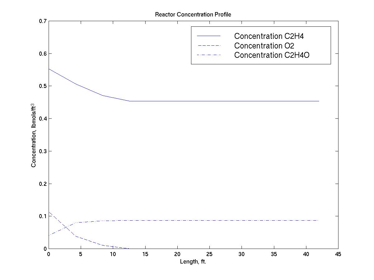
4.5.6 Reactor Concentration Profile
The reactor concentration profile below supports the fact that the
reactor is not limited by kinetics, since the reaction is at
equilibrium approximately 12 feet into the reactor:
4.6 Materials of Construction
4.6.1 Reactor Shell
The reactor shell should be constructed of carbon steel with a 1.25
corrosion allowance. Carbon steel is cheap and can easily
withstand the pressures and temperatures required for the shell side
of the reactor. During normal operations, the only fluid to
come in contact with the reactor shell will be industrial water.
4.6.2 Reactor Tubes
Since the reactor tubes will be in contact with ethylene oxide during
normal operations, the tubes should be constructed of 304 stainless
steel. The reaction of ethylene oxide and water to form
ethylene glycol is catalyzed by rust, and stainless steel will not
rust.
4.7 Combustion Inhibition
To inhibit the combustion of ethylene and maintain selectivity of the
ethylene oxide reaction, a few ppm of a chlorinated hydrocarbon, such
as ethyl chloride should be added to the reactor inlet
(Anderlik)(Meyers 1.5-3)
4.8 Recycle Loop Purge
The recycle loop inerts purge was set at 0.8% of the total molar flow
of the recycle stream after an iterative Aspen procedure determined
that this was the amount that removed enough methane to keep a
constant concentration of 38.7% mole in the reactor inlet.
5.0 Safety
5.1 Reaction System
To prevent explosive mixtures of hydrocarbon and oxygen in the
reactor, the recommended upper limits for ethylene and oxygen
in the reactor inlet are 40% and 9% by volume,
respectively. In order to achieve these concentrations, a
methane blanket on the recycle loop is required. (Meyers
1.5-3)(Davis). Methane is inert in this system. It does not
combust with oxygen since the selectivity of methane and ethylene
combustion leans heavily toward ethylene. This is because
ethylene is more reactive. In addition, since methane has a low
molecular weight it is easy to compress (Davis). Since an
ethylene oxide plant is compression limited, compression is a key
aspect.
5.2 Storage
5.2.1 Prevention of Backflow
The main safety concern in the reaction section is the backflow from
downstream reactors into ethylene oxide storage (Celanese Web).
If backflow does occur, catalyst widely used in downstream reactors,
such as KOH, can enter an ethylene oxide storage tank causing
violent, exothermic polymerization (Celanese Web). To avoid
this, a delta pressure instrument connected to a tight shutoff system
should be required on pipe between downstream users and storage
(Celanese Web). Furthermore, check valves should be installed
but not relied on for complete protection from backflow (Celanese
Web).
5.2.2 Storage Inertion
Ethylene oxide storage tanks should be blanketed with nitrogen
(Celanese Web). If this does not occur, ethylene oxide can
decompose explosively (Celanese Web). In addition, temperature
indicators should be present to indicate heat release from a
decomposition or polymerization reaction (Celanese Web).
5.3 Vent Gas Scrubber
To prevent the release of ethylene oxide to the atmosphere, any
process stream that goes to the atmosphere (including vent and
purges) should pass through a vent gas scrubber (Celanese Web).
This scrubber should consist of an absorber in which an aqueous
stream runs countercurrent to the flow of vent gas (Celanese Web).
5.4 Emergency Response
Emergency response teams should be made aware of the following:
¥ ethylene oxide can cause blistering, chemical burns,
irritation of exposed mucous membranes,
¥ ethylene oxide gas is volatile and flammable at atmospheric
conditions,
¥ the lower flammability limit concentration of ethylene oxide
in air is 2.6% and the upper flammability limit is 100%,
¥ a water-ethylene oxide mixture with a water to ethylene oxide
ratio of less than 22:1 is flammable,
¥ violent polymerization of ethylene oxide can occur, releasing
heat, and
¥ water is an acceptable fluid to deluge ethylene oxide vapors
with, but adding water to pools of liquid ethylene
oxide will cause more vapors to be
released (Celanese Web).
5.5 Safe Gasket, Packing, and O-Ring Materials
Ethylene oxide can attack and corrode many organic materials that are
routinely used in flange gaskets, valve packing, and seal o-rings
(Celanese Web). The following materials are recommended for
use:
¥ gaskets: Grafoil¨ and Stainless steel wound with
Teflon¨ filler,
¥ o-rings: Kalrex¨ 2035 and Teflon¨, and
¥ packing: Teflon¨, and Grafoil¨ GTB (Celanese
Web).
6.0 Economics
6.1 Cash Flow Analysis
A marginal discounted cash flow analysis was performed on the
expected cash flows of this reactor revamp project. In other
words, all costs and revenues were taken as the delta value from the
current value that the project would add. The rate of return of
the cash flow is 62.1% and the net present value of the cash flow is
$61,875,614, assuming a 13% cost of capital and twenty year operating
life. Since the rate of return is much higher than the cost of
capital and the net present value is much greater than zero, carrying
out this project would be economically sound. Please refer
to the appendix for the spreadsheets used. It was assumed
that procurement and construction of the reactors take place in first
quarter 1998, after detailed engineering design has been completed.
6.2 Installed Cost of Reactors
The installed cost of each reactor was calculated using a proprietary
Exxon cost estimation program. Since the program is
proprietary, output cannot be included in this report. The
assumptions and results, however, can be divulged. The program
assumed a 7 ft diameter, 42 ft long shell and tube heat exchanger
with carbon steel shell and stainless steel tubes. Triangular
tube pitch, 2 36Ó shell side nozzles, 2 24Ó tube side
nozzles, and a 304 clad carbon steel tube sheet were also
assumed. The installed cost of each vessel in fourth quarter
1996 dollars is $1,565,400. This cost was escalated by 4% a
year for two years to get the 1998 installed cost of each
reactor. A fudge factor of 5 was used to account for piping,
instrumentation, and addition equipment required.
6.3 Operating and Energy Cost
The only energy cost above the current energy costs is the cost of
the condensate used to cool the reaction. The May 1997 marginal
cost of condensate for the Exxon Baytown Refinery, $0.0562 per kgal
was used (Exxon B). This resulted in a yearly additional energy
cost of $4,525.
Additionally, operating costs were assumed to be 32% of the
installed cost (Dyson).
6.4 Reactant and Product Prices
Reactant and product prices are shown in table 6 below:
|
Compound |
Price |
Source |
|
C2H4 |
$0.25 per lb |
Chemical Week Web |
|
EO |
$0.42 per lb |
Chemical Week Web |
|
O2 |
$0.012 per lb |
Exxon C |
|
CH4 |
$0.0455 per lb |
Oilworld Web |
The reactor raw materials are available from neighboring sites. Specifically, ethylene is available by pipeline from the Exxon Baytown Olefins Plant, and oxygen is available by pipeline from the Air Products La Porte oxygen plant. Similarly, methane is available by pipeline from a variety of sources, including the Lyondell and Diamond Shamrock salt dome reservoirs in Mont Belview.
6.5 Consulting and Engineering Cost
JChem, Inc. engineering costs for this project are $1,000,000 and
additional consulting fees from Davis & Anderlik, LLP are
$50,000.
7.0 Conclusions and
Recommendations
JChem recommends that the current kerosene reactors be removed from
service. In their place, 3 shell and tube, recycled plug flow, water
cooled reactors should be installed in the first quarter of
1998. These reactors will alleviate the current heat removal
limitation and increase production to 1,000 mmlbs per year.
Increased production is desired in this market.
The future marginal cash flows have a rate of return of 62.1% and a net present value of $61,875,614.
The recommended reactors are specified in table 7.:
|
Volume of Process Side of Each Reactor |
1511 ft3 |
|
Tube Length |
42 ft. |
|
Tube Inner Diameter |
1.54 in. |
|
Tubes per reactor |
2781 |
|
Reactor Diameter |
7 ft |
|
Operating Inlet Temperature |
270 F |
|
Operating Outlet Temperature |
490 F |
|
Operating Inlet Pressure |
230 psig |
|
Operating Bed Pressure Drop |
20 psig |
|
Tube side service |
Ethylene, Oxygen, Methane, Ethylene Oxide |
|
Shell side service |
26.5 psig saturated water, 26.5 saturated steam |
|
Tube Material of Construction |
304 Stainless Steel |
|
Shell Material of Construction |
Carbon Steel |
|
Installed Cost, Per Reactor |
$1,692,704 |
|
Catalyst Type |
Shell Westhollow Silver |
|
Amount per Reactor |
20,772 lbs |
|
Life |
1,000 mmlbs EO |
|
Shape |
Cylindrical, (OD=1/4", ID=1/8", H=3/8") |
|
Packed |
Randomly |
|
Catalyst Replacement Cost, per Reactor per Year |
$3,974,210 |
¥ the use of methane to saturate the system and reduce risk
of explosion at reactor inlet,
¥ the prevention of backflow from upstream reactors to ethylene
oxide storage using a delta pressure instrument and shutdown
system,
¥ the inertion of ethylene storage tanks using nitrogen
¥ the use of a vent gas scrubber on all process vents and
purges, and
¥ the use of safe gasket, packing, and o-ring material such as
Grafoil¨, Kalrex¨, and Teflon¨.
JChem believes that the execution and completion of this project is
in the best economic interest of Celanese and recommends that this
project be carried out immediately.
8.0 References
Anderlik, J., Personal Interview.
Aspen Plus Ver. 9.3-1 On-line Help, PENG-ROB Property Option Set.
Berg, P.J. van den., deJong, W.A., Introduction to Chemical Process Technology, D. Reidel Publishing Company, Delft, Holland, pp. 188-198, 1979.
Bird, R.B., Stewart, W.E., Lightfoot, E.N., Transport Phenomena, John Wiley and Sons, New York, p. 391, 1960.
Celanese Web Site, Ethylene Oxide Users Guide, http://www.hcc.com/eo/contents.htm.
Chemical Week Web Site, Marketplace ProductFocus, http://www.chemweek.com/marketplace/product_focus/1996/eo_eg.html.
Davis, S.H., Personal Interview.
DeMaglie, B., ÒOxygen Best for EOÓ, Hydrocarbon Processing, Gulf Coast Publishers, March 1976, pp. 78-80.
Dyson, D., Ceng 302 Absorber Project Problem Statement, Spring 1995.
Exxon A, Exxon Design Practices, Exxon Research and Engineering, Section IX-B, p.19, 1996.
Exxon B, Ingram, D., Personal Interview.
Exxon C, Fruzzetti, M., Personal Interview.
Gans, M., Ozero, B.,ÓFor EO: Air or Oxygen?Ó, Hydrocarbon Processing, Gulf Coast Publishers, March 1976, pp.73-77.
Kiguchi, I., Kumazawa, T., Nakai, T., ÒFor EO: Air and Oxygen EqualÓ, Hydrocarbon Processing, Gulf Coast Publishers, March 1976, pp.69-72.
McKetta, J.J., Chemical Processing Handbook, Marcel Dekker, Inc., New York, pp.250-251, 1993.
Meyers, R.A., Handbook of Chemicals Production Processes, McGraw-Hill, New York, pp.1.5-1 - 1.5-13, 1986.
Oilworld Web, http://oilworld.com.tables