A plastic panel of area A=1 ft2 and thickness Y = 0.252 in. was found to conduct heat at a rate of 3.0 watts at steady state with temperatures of T0 = 24.00ēC and T1 = 26.00ēC on the two main surfaces. What is the thermal
conductivity of the plastic in cal sec-1 cm-1 (ēK)-1 at 25ēC?
Maple solution expanding on ex811.mws
> restart;
> A:=1*ft^2; Y:=0.252*inch; Q:=3*watt; T0:=(24+273.15)*K; T1:=(26+273.15)*K;
> dT:=T1-T0;
> k:=Q*Y/(A*dT); Equation 8.1-1

> watt:=J/s; ft:=12*inch; inch:=2.54*cm; J:=.23901*cal; Changing Units
> k; Solution for k (BSL calculates 2.47*10^-4 cal/(sec*cm*K)
> T:=y->a+b*y; Find a function T=T(y)
> eq1:=T(0)=T0; eq2:=T(Y)=T1;
> sol:=solve({eq1,eq2},{a,b});
> assign(sol); T(y);
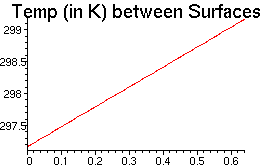
> Tf:=xi->simplify(T(xi*cm)/K); Tf(xi); Plotting in MAPLE requires that we have a numerical function with a numerical argument.
> plot(Tf(xi), xi=0...Y/cm, labels=["y in cm",""], title="Temp (in K) between Surfaces", labelfont=[TIMES,ROMAN,12], titlefont=[HELVETICA,14]);

Now that we have k, we can calculate the local heat flow per unit area (heat flux) in the positive y-direction using eq. 8.1-2
> dTdy:=diff(T(y),y);
> qy:=-k*dTdy;
Also, we can calculate the thermal diffusivity of the plastic. In this case, let's assume a polyethylene panel, with specific weight 0.95 and heat capacity 2100 J/(kg*K).
Thermal diffusivity = k/(r*CP)
> k;
> Cp:=2100*J/(kg*K);
> rhoPl:=sw*rhoH2O;
> sw:=0.95;
> rhoH2O:=1.0*g/cm^3;

> rhoPl;

> g:=.001*kg;
> alpha:=k/(rhoPl*Cp);

There are five main methods that are used to measure the thermal conductivity of materials (for more information, see http://mathis.unb.ca/hotdisk/hda7card.html,
http://www.tprl.com/flash.html,
and http://www.psrc.usm.edu/macrog/dsc.htm):
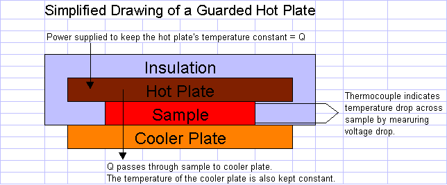
1. Guarded Hot Plate: A solid sample of the material is placed between two plates. One plate is heated, and the other is cooled or heated to a lesser extent. Once the system has reached a steady state, thermocouples measure the temperature drop across the sample (dT in ex 8.1-1). The heat flow through the sample (Q in ex. 8.1-1) is equal to the power supplied to the hot plate to maintain its steady-state temperature.
2. Hot Wire: A heated wire is inserted into the material, and the temperature change in the wire is recorded. When Cp and density are known for the substance, the plot of Twire vs. ln(time) can be used to find the thermal conductivity of the sample. Since this is an intrusive measure, it cannot be used for solids; it works well for foams, fluids, and melted plastics.
3. Modified Hot Wire: In this case, the hot wire is supported on backing, so the wire does not have to actually penetrate the sample. This modification allows for the testing of solid samples. The calculation of k is similar to that in the hot wire procedure.
4. Laser Flash Diffusivity: A laser flash delivers a short pulse of heat to the front of the sample, and an infrared scanner observes the temperature change at the rear face as a function of
time. The thermal diffusivity of the sample is then determined from the
following relation:

where t1/2 is the amount of time from the beginning of the laser pulse to the moment the rear-face temperature rise is one-half its maximum, and L is the thickness of the sample. The thermal conductivity of the sample can then be calculated from the definition of thermal diffusivity if the density and heat capacity of the sample are known:

5. Modulated Differential Scanning Calorimetry (DSC): The sample is placed in a pan. Heaters raise the temperature of the sample pan and a reference pan at the same rate. The apparent heat capacity for the sample can be measured from the different amounts of heat put into the two trays to raise their temperatures at the same rate. A DSC measurement is made on two samples of varying thickness. The difference in apparent heat capacity is caused by the time lag of heat passing through the sample. The DSC results and the different thicknesses can be used to find the thermal conductivity of the material.
Example 8.1-1 indicates that a steady-state test was performed on a solid piece of plastic. The guarded hot plate method would be ideal for this type of measurement. From visiting various web sites, I found that a 1ft x 1ft sample is approximately nominal size for most commercial guarded hot plates.
