PERFORMANCE CURVES OF AN INTERNAL COMBUSTION ENGINE
(MEMS Dept., Rice University)
PERFORMANCE CURVES OF AN INTERNAL COMBUSTION ENGINE
(MEMS Dept., Rice University)
Object
The purpose of this experiment is to conduct a variable-speed, open throttle test of a spark ignition internal combustion engine, and record data points for the power, torque, specific fuel consumption (SFC), and thermal efficiency curves.
Apparatus
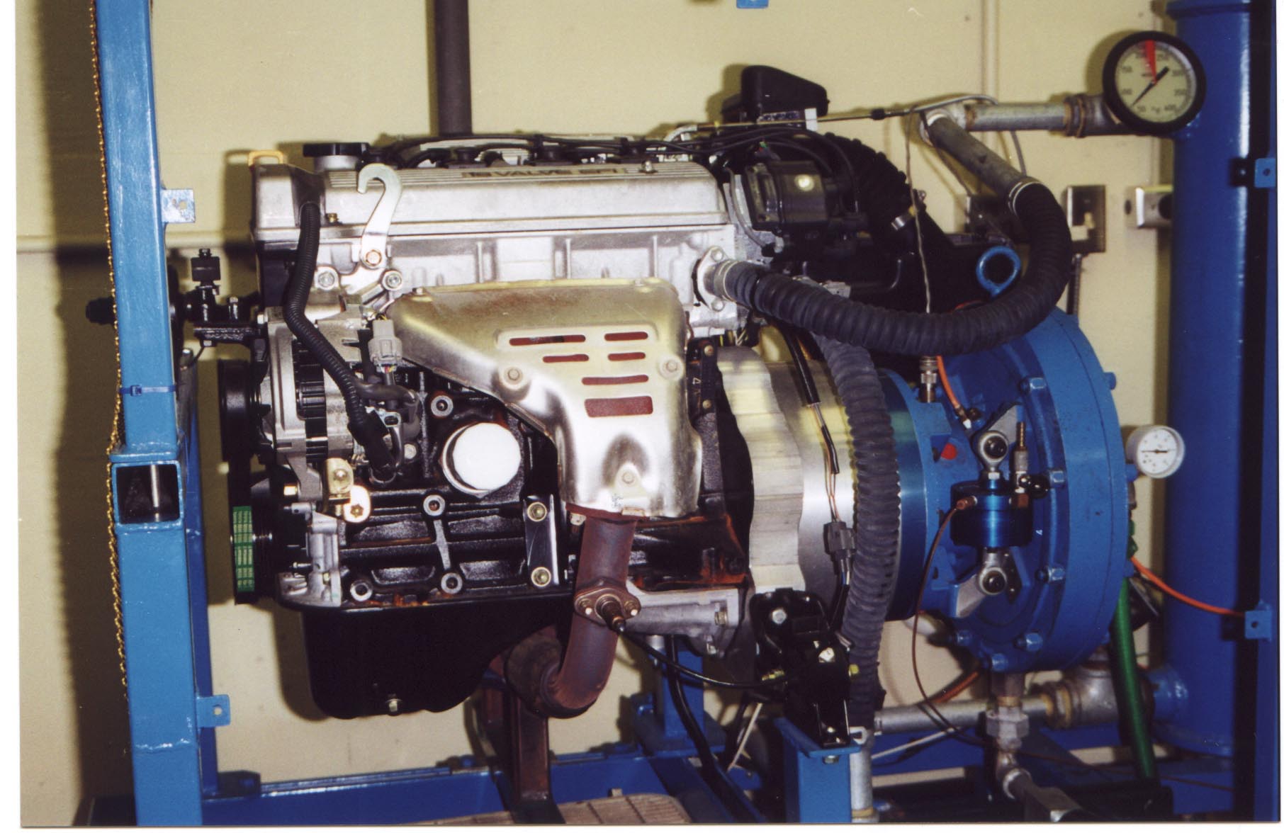
(1) Engine and water brake dynamometer located in
the power lab;
(2) Stopwatch;
(3) Ear protection: ear protectors should be worn during all test
runs.
Procedure
For a maximum-power test on a spark ignition engine, the throttle is fully opened and the desired speed is maintained by the water brake dynamometer. The engine is run for a period of time until it has been brought to equilibrium. When thermal equilibrium has been established, the test is started.
The procedure is to establish fuel consumption based on the mass of fuel consumed within a specified period of time. Furthermore, to minimize fuel consumption and exposure to the hot, noisy test environment, each lab group will make two test runs. Each group will get an additional set of data points for this engine. Reports are to be based on the entire data set. Each group will make test runs within the following speed ranges:
Speed Range (rpm)
First data point 1200--1800
Second data point 3000--4000
Additional data points Instructor specified
Test Equipment
Engine
See data on the Toyota 4A-F engine at end of the handout. The listed values are for the engine installed in a vehicle (SAE-Net). Therefore, do not be surprised if your results for torque and horsepower are somewhat different.
Dynamometer
The energy-absorbing device used in this experiment is a Kahn Industries Inc. water brake dynamometer Model 101-130-003. The device has a capacity of 1000 hp. The maximum speed is 9000 rpm and the maximum torque is 600 ft/lb.
The dynamometer contains one perforated disc, which rotates in a housing between a similar set of perforated stators. Cold water enters the rotor chamber at the center. The water is accelerated by the rotating disc and thrown outwards by centrifugal action. From the outer diameter of the rotor chamber inwards, the water forms an annulus that rotates at approximately half the disc speed. Hot water is discharged through a hole located at the bottom of the housing.
Power is absorbed through the turbulent motion developed inside the device. The resulting drag acts as a resistance to rotation and tends, with an equal effort, to turn the dynamometer housing. The housing is restrained from turning by a load cell, which is mounted at a fixed distance from the centerline of the dynamometer. This load cell measures the output torque of the engine.
Operating Instructions
THIS LAB WILL LARGELY BE DONE AS A DEMONSTRATION BUT THE LAB INSTRUCTIONS ARE AS FOLLOWS:
A. First, familiarize yourself with the various
control valves for the engine and dynamometer.
Locate:
(1) Engine coolant input valve (should not need adjustment)
(2) Dynamometer seal coolant needle valve
(3) Dynamometer loading valves (coarse and fine adjustment valves)
(4) Dynamometer drain valve (large, black-handled needle valve)
(5) Engine throttle (aircraft style)
(6) Ignition switch (key switch)
(7) Starter button.
B. You are now ready to start your engine.
(1) Confirm with the lab assistant that the dynamometer drain valve is open at least 1 1/2 turns. (2) Turn the ignition switch ON (key switch).
(3) Turn the fuel pump on (toggle switch with green indicator light).
(4) Press the start button until the engine fires.
C. Once the engine is started, watch the following very carefully:
Engine coolant temperature: not to exceed 210_F. (Note red line on the gage.)
Engine rpm (on test control panel): not to exceed 6000 rpm.
Dynamometer seal coolant flow: about 6. (Keep ball at or above the red line.)
Dynamometer drain temperature: not to exceed 140_F.
Water is coming out of the two hoses run out the service door of the lab.
D. Let the engine idle for about five minutes until it warms up. During this time, familiarize yourself with taking data:
(1) The torque is read from the gage on the test control panel. If it should fluctuate at higher speed, the vibrations can be damped with the damping valve on the left side of the box.
(2) The engine temperature is read from the thermometer on the test control panel.
(3) The fuel pressure is read on the digital pressure (psi) gage also on the test control panel
(4) Work out a set of hand signals to be used during testing for shutting the gasoline supply valve, shutting down the engine, etc.
E. Once the engine is warmed up, the testing may begin. Put on ear protection devices. Before the throttle is opened, the engine must be loaded with flow through the dynamometer.
(1) Open the dynamometer-loading valve slowly while opening the throttle. Increase the throttle opening until the target rpm is reached.
(2) Continue opening the dynamometer loading valve (fine adjustment) slowly (which reduces rpm), and open the throttle (to re-gain rpm) in small increments. Repeat this process until the throttle is completely open.Once the engine is stabilized at full throttle, close the green gasoline supply valve at the top of the fuel sight glass. Start the stopwatch and record gasoline pressure. At the end of the time interval, record the gasoline pressure. Record the average rpm and torque reading during the interval. Also, note the engine temperature at the beginning and end of the interval. Use the temperature gage on the test control panel for recording engine temperature.
F. Make sure the engine speed does not exceed 6000 rpm during any test.
Shutting the Engine Down
IN AN EMERGENCY, TURN THE IGNITION OFF.
For a normal shutdown:
1. Close down the throttle until the engine is at idle.
2. Close down the dynamometer-loading valve to reduce the load on the engine.
3. Turn the ignition and fuel pump switches OFF.
4. Close down all the supply valves and turn off the fan. Close the gas supply valve.
Individual Report
The following graphs will be provided: 1) Torque vs. rpm, 2) Brake Horsepower, and 3) Thermal Efficiency vs. rpm.
Follow the Individual Report Outline (to be supplied). Compare the maximum brake horsepower and torque values with the same quantities listed in the engine specifications. Answer any questions associated with this experiment in your discussion section.
Reference
[1] Stone, Richard: Introduction to Internal Combustion Engines, Second edition, SAE, Warrendale, PA, p. 65, 1992.
Toyota 4FA Engine Specifications
Number of Cylinders &
Arrangement……………. 4-Cylinder, In-line
Valve Mechanism
………………………………… 4
Valves, DOHC, Belt & Gear Drive
Combustion
Chamber……………………………… Pentroof
Type
Bore x Stroke in. (mm)
…………………………. 3.19 x
3.03 (81 x77)
Displacement cu. In.
(cc)………………………… 96.8
(1587)
Compression Ratio
……………………………... 9.5:1
Max. Engine Power Output (SAE-Net)………… .... .....
90 Hp @ 6000 rpm
Max. Torque Output
(SAE-Net)…………………. 95 ft-lbs.
@3600 rpm
Fuel Octane Number (RON)
…………………….. 91
Appendix A
(For Reference Only; Not Required for BAKE 169 Lab)
Data and Calculations
As stated earlier, during each test record the following:
1. Run duration time (sec.)
2. Average speed (rpm)
3. Average torque (gage reading times 1.19 gives ft-lb.)
4. Temperatures (°F)
5. Initial and final fuel supply pressures (psi) during timed interval. (One-half minute interval is preferred).
For your test results and the instructor-supplied test results, calculate the Brake Horsepower, engine Output Torque, and thermal efficiency for each of the data points. The following relations should be helpful:
BHP = (T)(n)/5252
where
n = engine speed in rpm.
T = torque in lb.-ft.
Note: torque in ft-lb. = gage reading times 1.19
Thermal Efficiency = (Energy Output)/(Heat Input)
where
Energy Output (BTU/hr) = BHP x 2544.43
Heat Input (BTU/hr) = Fuel Rate x Heat Content of Gasoline (19,ooo BTU/lbm)
Fuel Rate (lbm/hr) = (reading (1) - reading (2)) x Area of Tube X 3600/t
t = test interval in seconds
Ai = (Pi)(Di^2)/4
where:
Di = internal diameter of gasoline tube = 0.750 in.