Project Flow Diagrams
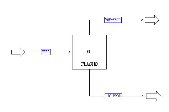
In previous discussion, the differences between a non-PFD drawing and a PFD drawing were briefly mentioned. PFD stands for project flow diagram. In Aspen, you may enter PFD mode to spruce up your model for a presentation. For instance, a non-PFD drawing of the flash system may look something like this.

|
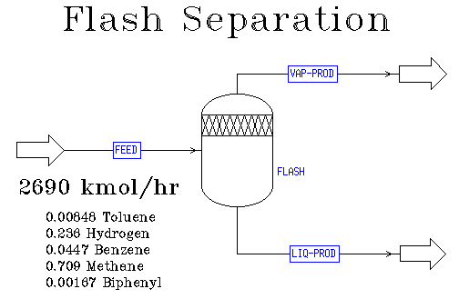
We may employ the PFD features of Aspen to make our model like this.

|
To enter PFD mode, click on the "PFD" button in the upper-right hand corner of the main Aspen window. You should notice that doing this changes the appearance of the right-hand side of the Aspen window. What appears is a menu similar to other drawing programs. With this menu, you may alter your model to make it look better for presentations. For example, the add the title "Flash Separation" across the top of the model, select the big "A" that is just under the word "Tools." Doing this causes your cursor to turn into crosshairs. Place the crosshairs on your diagram where you want the text appear. Aspen will then ask you to enter you text. After you hit return, your text will be placed on the diagram where the crosshairs were. You may always edit text by clicking on it with the left mouse button. Once you have done this, you may move the text with the arrow keys. You may change the size of the text with the +/- keys. To edit the text, click on the right mouse button and choose "Edit text" from the menu.
Once you are finished spicing up your picture, you may click on the "PFD" button to return to the basic picture of the model. Keep in mind that doing this does not erase your PFD. Also, you may always execute models whether or not you are in PFD mode.
This should give you an idea of how to create Project Flow Diagrams in Aspen. While this section is not exhaustive, it should point you in the right direction for creating presentation materials.