Now that you have seen the majority of the pieces of equipment you will use during CENG 403, it is time to create a model using Aspen. The example presented here is the same as the one discussed in the section on flash separations in Aspen, except that the version here is more detailed so that you will become more familiar with Aspen.
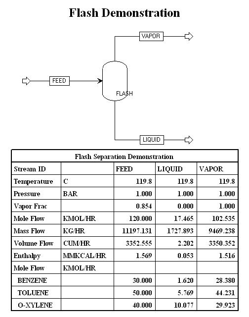
Below is a diagram of a flash separation unit in Aspen. We will demonstrate the steps needed to create such a diagram in an Aspen session.
This flow diagram was created in the following manner:
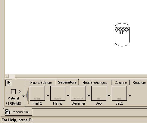
At this point the left/bottom part of the window should look something like:
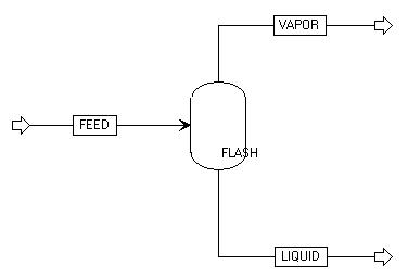
The flow diagram might look like this:
At this point, the first step in creating a model in Aspen,
drawing a flow diagram, is complete. Click on the word "Next" icon:
![]() in the upper-right-hand part of the Aspen window. A window should
appear announcing that the "Flowsheet connectivity is complete."
Click on the "OK" button.
in the upper-right-hand part of the Aspen window. A window should
appear announcing that the "Flowsheet connectivity is complete."
Click on the "OK" button.
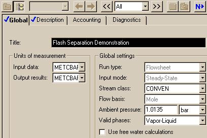
The next window to appear is the Setup Specifications window. For this example, no action is required, but we can add a "Title" and change units to be used globally. This is the way the window looked for our demonstration.
Note that the "setup" Folder is checked so we can go on to the next window by clicking the "Next" icon.
This next window is where you tell Aspen which components will be in the system. Fill in the window such that it looks like this:
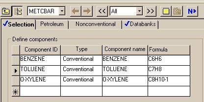
Once your component window looks like this one, click on the "Next" button again. The next window to appear allows you to specify which thermodynamics package you want to use to model the system. For this system, choose the ideal package. To do this, select "IDEAL" in the "Property methods & models" section as the "Base Method".
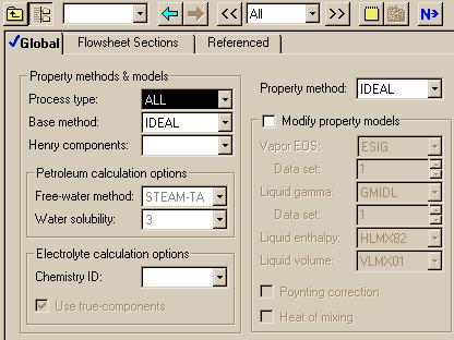
Once again, where you are finished with the window as shown by the check for "Properties" so you can hit the "Next" button. When you do so, you will encounter a message saying the required properties input is complete and you have to verify that you want to go on to the next "required" step.
Now we need to specify the conditions of the feed stream. For this example, we will use 393 K and 1 bar.
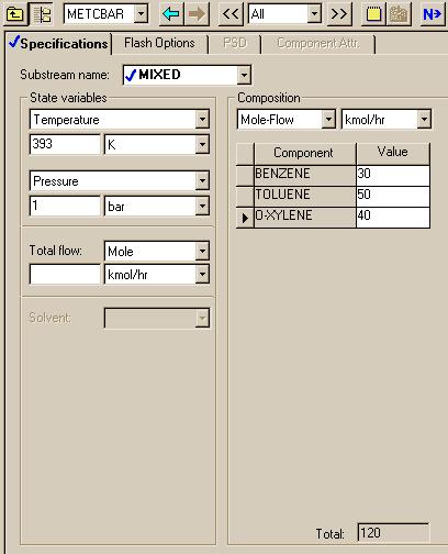
After you fill in your Stream FEED Input window, click on the "Next" button. The next window to appear is the last window for this system. In this window, you need to specify the conditions of the flash. For this example, we will use 393 K and 1 bar: the same numbers used in the first run in the section that deals with flash tanks in Aspen. This window should look like this:
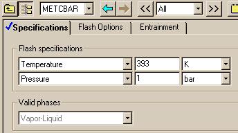
Once you have done this, you have finished creating the model. To run the model, click on "Next," which causes Aspen to inform you that the required input is complete. Now choose "OK."